Matrix MX-A5x Specifications Page 12

  • Download
  • Add to my manuals
  • Print
  • Page
    / 27
  • Table of contents
  • BOOKMARKS
  • Rated. / 5. Based on customer reviews
Page view 11
4.2 MANAGER SCREEN DESCRIPTIONS
• P0: Maximum progam time -
Sets the total run time of any program.
• P1: Default workout time -
Workout time when QUICK START is pressed or when no time is
selected during program set up.
• P2: Default resistance level -
Starting resistance when QUICK START is pressed or no resistance
level is selected during program set up.
• P3: Default user weight -
Weight used for program calorie expenditure calculations.
• P4: Speed Units - Display value in miles or kilometers.
• P5: Machine Type -
Console is shared between the A5x and I5xi. A5x default setting is
“SWING” and I5xi default setting is “RAMP
”.
• P6: Console beep on / off - Confirmation beeps can be turned on or off.
• P7: Accumulated distance - Total distance of all programs.
• P8: Accumulated time - Total accumulated program time displayed in hours.
• P9: Display language -
Select between English, Spanish, French Italian, Dutch and German.
• P10: Software version -
Current version of software. Refer to this when calling Matrix Technical Service.
• P11: Incline calibration -
Default display is OFF. Selecting ON will automatically calibrate the
incline motor (s) to factory settings. Use this feature when actual
elevation does not match console display.
• P12: Incline Reset -
This is a software feature that resets machine elevation to 0 degrees
after 30 seconds of user inactivity. During incline reset, movement
can be stopped by pressing any console key. Display will scroll “HOLD
SELECT TO RESUME”. To resume reset to 0 degrees, hold “SELECT”key
for three seconds.
• P13: Default incline level -
Starting incline level at each program start except FIT TEST.
Factory setting is 10%. In FIT TEST, elevation is set to 0%
.
• P14: Error Code -
Console will record up to three errors. Error codes are stored permanently
unless reset by a technician. To reset error codes, hold MANUAL and
RANDOM keys for three seconds. Refer to these error codes when
calling Matrix technical service for assistance.
• P15: LCB Version -
Display will show LCB.VER XX YYY.
XX is machine type.
YYY is version number.
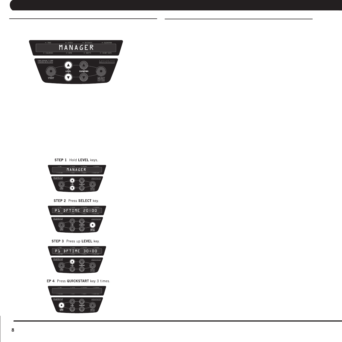
4.1 USING MANAGER MODE
• To enter manager mode, hold the UP and DOWN level keys for three
seconds until “MANAGER” appears on the middle LED display.
•
Press the UP and DOWN elevation keys to scroll between program screens.
• Press SELECT to modify program setting.
• Press UP or DOWN level keys to change value.
• Press QUICK START to save setting.
• Press QUICK START again to exit manager mode.
(example changing default time from 20:00 - 30:00 minutes).
QUICKSTAR T
CHAPTER 4: Programming & engineering mode
Page view 11
1 2 ... 7 8 9 10 11 12 13 14 15 16 17 ... 26 27

Comments to this Manuals

No comments

Vax Power 6 SERIES podręczniki

Instrukcje obsługi i podręczniki użytkownika dla Odkurzacze Vax Power 6 SERIES.
Dostarczamy 1 pdf podręczników Vax Power 6 SERIES do pobrania za darmo według typów dokumentów: Przewodnik Instalacji


Vax Power 6 SERIES Przewodnik Instalacji (199 strony)


Marka: Vax | Kategoria: Vacuum cleaners | Rozmiar: 0.76 MB |


Spis treści

Order Number EK–600EB–IN.002

1

Contents

3

Chapter 7 System Self-Test

5

Chapter 8 Verification

5

Intended Audience

11

Document Structure

11

VAX 6000 Series Documents

12

Title Order Number

13

Operation

13

Service and Installation

13

Options and Upgrades

13

Associated Documents

14

System I/O Options

15

Operating System Manuals

16

VAXclusters and Networking

16

Peripherals

17

VAX Manuals

17

Site Preparation

18

Slots Function

20

154 CM (60.5 IN)

21

Figure 1–2: Airflow Pattern

23

1.3 Cabinet Sizes

24

Site Preparation 1–9

25

1.4 Power Requirements

26

Table 1–5: Power Requirements

27

Unpacking

29

2.1 Inspect the Shipment

30

Item Use

32

Tool Use

33

2.4 Remove from the Pallet

36

2.5 Leveling the Cabinet

38

HEX WRENCH

39

TERMINAL

40

ETHERNET

42

2.8 Connect the FDDI Cable

44

Chapter 3

47

Table 3–1: DSSI Documentation

48

Table 3–2: DSSI Installation

49

DEMNA KFMSADEMFA

51

3.4 DSSI Basics

54

Term Reference Definition

55

3.4.1 KFMSA Adapter

56

DSSI Bus 1

58

DSSI Bus 2

58

3.4.3 SF7x Enclosure Box

60

3.4.5 Single-Host Systems

64

Table 3–5: KFMSA Options

69

Table 3–6: DSSI Cable Kits

69

KFMSA NODE ID

72

SELECT KNOB

72

3.5.2 Set Node IDs

74

Power Up System.

76

Self-Test Runs

76

Table 3–7: VAX/DS File Names

79

3.6.3 Example: Run EVCXF

82

Connecting to a CI VAXcluster

88

4.1 CI Adapter Overview

89

Standard or

90

Optional Function

90

4.3 Setting CIXCD Parameters

93

Boot Time

99

Arbitration (Optional)

101

SECTION D

103

Cluster

103

4.4 Setting CIBCA Parameters

105

SECTION E

107

OUT OUT OUT OUT IN OUT OUT IN

108

TRANSMIT

111

CONNECTORS

111

RECEIVE

111

Connecting to Tapes and Disks

114

5.1 Architecture

115

Adapter Bus

116

Installation

116

Instructions Connects to

116

5.2 Cabling TU Tape Drives

117

CONTROLLER

119

Powering Up the System

122

6.1 Prepare the Cabinet

123

6.3 Check the Power

127

Powering Up the System 6–7

128

LED Condition Color Meaning

130

Powering Up the System 6–11

132

Table 6–2: Upper Key Switch

134

Table 6–3: Lower Key Switch

134

6.5.2 Restart Button

135

Table 6–4: Restart Button

136

6.5.3 Status Indicator Lights

137

msb-0124-91

137

Light Color State Meaning

138

System Self-Test

140

Verification

148

8.1 Console Load Devices

149

Model 3/400

151

Site Management Guide

152

SELF-TEST OK LED

155

CONNECTOR

155

EXTERNAL

155

LOOPBACK LED

155

BOOT /XMI:m

159

ISL_LVAX_x

159

BOOT /R5:10 CSA1

160

Table 8–2: VAX/DS File Names

166

Model Number

168

File Name

168

8.8 Set Boot Devices

169

8.9 Record System Parameters

171

System Method

172

Example 8–9: Running UETP

173

Module Handling

177

B.1 Handling Modules

178

B.2 Inserting Modules

180

Appendix C

183

C.1 Prepare the Cabinets

184

TOP COVER

185

C.2 Join the Cabinets

186

XMI-to-VAXBI Adapter Cables

188

Table C–1: Cable Connections

189

C.5 DWMBB Cabling

192

DSSI Configuration Sheets

193

DSSI Configuration Sheets D–3

195


Więcej produktów i instrukcji dla Odkurzacze Vax

Modele Rodzaj dokumentu
U86-PM Series Podręcznik Użytkownika   Vax U86-PM Series User guide, 20 strony
VCW-01 Podręcznik Użytkownika   Vax VCW-01 User guide, 16 strony
Rapide VX30 carpet washer Fresh Instrukcja Użytkownika   rapide-plus-5130 [en] , 8 strony
VZL-704 Podręcznik Użytkownika   Vax VZL-704 User guide, 12 strony
C90-P2 SERIES Podręcznik Użytkownika     Vax C90-P2 SERIES User guide, 148 strony
V-106AA Instrukcja Obsługi   Vax V-106AA Technical data, 120 strony
C90-MVX Series Instrukcja Użytkownika   File Extensions for Collection Categories, 203 strony
V-044 Podręcznik Użytkownika   Vax V-044 User guide, 12 strony
U90-CX-P-A Podręcznik Użytkownika   Vax U90-CX-P-A User guide, 20 strony
C91-MX SERIES Podręcznik Użytkownika   Vax C91-MX SERIES User guide, 12 strony
U90-P6 Series Podręcznik Użytkownika   Vax U90-P6 Series User guide, 16 strony
Rapide VX30 carpet washer Fresh Podręcznik Użytkownika   Vax Rapide VX30 carpet washer Fresh User guide, 11 strony
V-002 Instrukcja Użytkownika   Vax V-002 User`s manual, 228 strony
U88-VU-R-A Podręcznik Użytkownika   Vax U88-VU-R-A User guide, 12 strony
Bagged Cylinder Podręcznik Użytkownika   Vax Bagged Cylinder User guide, 12 strony
VHFM700 Podręcznik Użytkownika   Vax VHFM700 User guide, 16 strony
VEC-105 Podręcznik Użytkownika   Vax VEC-105 User guide, 52 strony
6121 Multivax Podręcznik Użytkownika   Vax 6121 Multivax User guide, 16 strony
C90-P2 SERIES Dokumentacja   Vax C90-P2 SERIES Specifications [en] , 288 strony
U88-VU-T-A Podręcznik Użytkownika   Vax U88-VU-T-A User guide, 12 strony